Optimized Synthesis Conditions of Polyethersulfone Support Layer for Enhanced Water Flux for Thin Film Composite Membrane
Article information
Abstract
Different types of polyethersulfone (PES) support layer for a thin film composite (TFC) membrane were synthesized under various synthesis conditions using the phase inversion method to study the combined effects of substrate, adhesive, and pore former. The permeability, selectivity, pore structure, and morphology of the prepared membranes were analyzed to evaluate the membrane performance. The combined use of substrate, adhesive, and pore former produced a thinner dense top layer, with more straight finger-like pores. The pure water permeation (PWP) of the optimized PES membrane was 27.42 L/m2hr (LMH), whereas that of bare PES membrane was 3.24 LMH. Moreover, membrane selectivity, represented as divalent ion (CaSO4) rejection, was not sacrificed under the synthesis conditions, which produced the dramatically enhanced PWP. The high permeability and selectivity of the PES membrane produced under the optimized synthesis conditions suggest that it can be utilized as a potential support layer for TFC membranes.
1. Introduction
Recently, 80% of the world’s population live in regions where water security poses a threat [1]. Population growth, industrialization, contamination of available freshwater resources, and climate change are all accelerating water scarcity [2]. To address the problem, seawater desalination has been received great attention due to the plentiful supply seawater [3–5]. Additional advantages of desalination are the compact of process, high water quality, and low operating cost. Current approaches to desalination include membrane-based technology, distillation, freezing, and the ion exchange method [6–8]. In membrane-based seawater desalination, thin film composite (TFC) membranes are widely used due to their reduced internal concentration polarization, which results in high water flux, and their high mechanical strength [9].
Generally, TFC membranes are composed of an active layer, support layer, and substrate [10–12]. Polyamide membranes, produced by interfacial polymerization, are widely used as the active layer due to their high water flux and salt rejection, both highly desirable properties of membranes for seawater desalination [9]. To deposit polyamide layer on the membrane surface, a high acid resistance polymer is required as the support layer. Polysulfone (PSU) is considered as good candidate as a support layer due to its high acid resistance, mechanical strength, and water flux [13].
However, it has been recently reported that polyethersulfone (PES) produces more finger-like pores than PSU due to the former’s higher polarity and hydrophilicity, thereby enhancing water flux. In addition, PES membranes have a higher mechanical strength than PSU ones due to the high flexibility of the polymer, something that is needed in a water treatment membrane [14]. Therefore, PES is considered a strong candidate as a support layer of TFC membranes. Moreover, the substrate layer is essential component for the TFC membrane to resist high pressure in the desalination process. A nonwoven fabric matrix is widely used as a substrate in this process due to the fabric’s extremely high mechanical strength.
To date, in-depth research on PES support layer synthetic conditions with or without nonwoven fabric substrate for TFC membrane has not been revealed. During the support layer casting step for TFC membrane, the polymer solution can readily penetrate into the substrate because of its large pore size. The adhesive solvent, which is used to make a strong bond between the support layer and the substrate, can accelerate penetration phenomena. Bottom macro void of support layer can penetrate into the substrate and thickness of support layer can be reduced due to the effects of substrate and adhesive solvent. Thus, maximizing the performance of TFC membranes for seawater desalination requires optimizing the synthesis conditions of components of the support layer, such as the presence of substrate or adhesive.
As a pore former, the effects of polyvinylpyrrolidone (PVP) on the performance of PES membranes with regard to water flux or rejection have been studied [15]. It produces a thin top dense layer during the phase inversion step and increases membrane hydrophilicity due to its inherent hydrophilicity [16–20]. However, the combined effects of substrate, adhesive, and pore former on PES in TFC membranes have not been studied so far.
Therefore, we synthesized different types of PES membrane via the phase inversion method under different synthesis conditions (i.e., with and/or without the presence of substrate, adhesive, and pore former). In addition, we determined the permeability, selectivity, and morphology of the resulting PES membrane, which can be utilized as a support layer for TFC membranes in a further.
2. Materials and Methods
2.1. Materials
Deionized (DI) water was prepared using a water purification system (Synergy; Millipore, USA) with resistivity of 18.2 mΩ-cm at 25°C. An ultrasonicator (B8510-MT; Branson, USA) was used to remove invisible air bubbles in the polymer solutions.
PES (H-2000; Solvay, Korea) with a molecular weight (Mw) of 62,000–64,000 g/mol was used for PES membrane synthesis. The solvent was n-methyl-2-pyrrolidinone (NMP) (anhydrous 99.5%; Sigma-Aldrich, USA), and PVP (Mw: 10,000 g/mol; Sigma-Aldrich, USA) was used as a pore formation additive. Polyethylene terephthalate (PET) nonwoven fabric was used as substrate (AMFOR Inc., USA). NMP was also used as an adhesive to strongly bind the PES layer and PET substrate. A casting knife, made of laser precision-machined iron, was used to obtain membranes with a constant thickness. To evaluate the membrane permeability, a pure water permeation instrument was installed at the cross flow of assembled aryl cells (Millipore, USA). Divalent salt, CaSO4·2H2O, was dissolved in DI water to evaluate the membrane selectivity (BioXtra >98.0%; Sigma-Aldrich, USA). An atomic force microscope (AFM) was used in contact mode to evaluate the morphology and roughness of the prepared membranes (603–1001; Park systems, Korea).
2.2. Synthesis of PES Membrane
In this study, PES membranes were synthesized via phase inversion, which is a widely used method in organic polymer membrane fabrication. They were synthesized under different synthesis conditions, such as the presence of substrate, adhesive, and pore former. The synthesis conditions of the PES membranes are summarized in Table 1. To make the PES membranes, PES powder was heated in an oven at 100° C for 1 hr to remove all moisture, which could influence the performance of the membrane during phase inversion. Then, 25 wt.% of PES powder in a ratio to total casting solution was dissolved in the NMP solvent for 3 hr. Following this step, the prepared solution underwent ultra-sonication to remove invisible air bubbles. The membrane casting step was followed by a casting knife with 200 μm thickness on a glass plate. Finally, casted membrane was immersed into a water bath to promote phase inversion between the NMP solvent and the DI water.

Synthesis Conditions of polyethersulfone (PES) Membranes
Different types of PES membranes (PES2, PES3, PES4, and PES5) were prepared under different synthesis conditions (Fig. 1). The prepared casting solution was poured on the PET substrate in the PES2 membrane without any treatment with additives. For the synthesis of PES3 membrane, the PET substrate was wetted with NMP before pouring the casting solution onto the PET substrate. NMP was used as an adhesive between the casting solution and the PET substrate. In PES4, 1 wt.% of PVP as a pore former was added into the casting solution. Both adhesive and pore former were applied for the synthesis of PES5 membrane. All the synthesized membranes were stored in DI water for one day to remove solvent remaining inside the membrane prior to further experiments.
Schematic of synthesis conditions of polyethersulfone (PES) membranes with or without substrate (PET), adhesive (NMP) and pore former (PVP). PES2 membrane has substrate only. PES3 membrane has both substrate and adhesive. PES4 membrane has both substrate.
2.3. Lab-scale UF Filtration
Lab-scale cross-flow UF filtration was carried out to measure the water flux of the PES membranes. The effective membrane area of each cell was 18.56 cm2, the temperature was kept at 20°C, and the circulation flow was maintained at 400 ccm. All the membranes were stabilized at a trans-membrane pressure (TMP) of 4.14 bar (60 psi) for 4 hr, and then the TMP was kept at 4.14 bar for 3 h to examine the water flux. The schematic of the lab-scale cross flow UF set-up is illustrated in Fig. 2. To evaluate the membrane selectivity with regard to rejection of divalent ions, the following equation was employed:

Schematic of lab-scale cross-flow UF instrument.
where R is the CaSO4 rejection, and Cf and Cp are the concentrations of the feed water and permeate, respectively. The CaSO4 rejection rate was calculated by measuring the conductivity and converting the values using a correlation curve between the conductivity and concentration of CaSO4 (Fig. 3.). Fig. 3 shows that CaSO4 was fully dissolved in DI water with concentration less than 200 ppm.

Correlation curve between conductivity (μS) and CaSO4 concentration (ppm).
2.4. Analysis of Membrane Structure and Surface Morphology
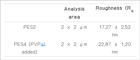
The membrane thickness and pore structure were measured by scanning electron microscope (SEM). The membrane was fully dried at 40°C for one day in an oven and immersed in liquid nitrogen. The frozen membrane was then broken, and its cross-section was measured with SEM. The surface morphology and roughness of the prepared membranes were measured with an AFM. The analyzed areas were 2 μm × 2 μm, and the membrane surface roughness was expressed as root mean square, Rq (Table 2). The AFM experiment was conducted in contact mode using contact cantilever tips.
3. Results and Discussion
3.1. Effects of Substrate on PES Membrane
Substrate effects were observed in the PES2 (with PET substrate) and PES membranes (without PET substrate). The thickness of PES2 membrane was thinner (109 μm) than that of the PES membrane (171 μm) due to the penetration of the casting solution into the PET substrate during casting step (Fig. 4. (a), (b)). The pure water permeation (PWP) of the PES2 membrane was 5.63 L/m2hr (LMH), whereas it was 3.24 LMH for the PES membrane (Fig. 5.). Therefore, the use of the PET substrate resulted in a thinner PES layer formation, which enhanced the PWP of PES2 membrane. In addition, only narrow finger-like pores were observed on the PET substrate which results in thin PES layer formation, since that macrovoids were formed in the substrate matrix due to the PES solution penetration into the PET substrate. This thin layer and enlarged inside pore structure contributed to enhance PWP simultaneously.

Scanning electron microscope (SEM) images of synthesized polyethersulfone (PES) membrane (a) PES, (b) PES2, (c) PES3, (d) PES4, and (e) PES5.

Pure water permeation (PWP) of synthesized membranes following a UF filtration test for 3 hr.
3.2. Effects of Adhesive on PES Membrane
Adhesive was used in the PES3 but not the PES2 membrane. The PES3 membrane was significantly thinner (46 μm) than the PES2 membrane (109 μm) due to accelerated penetration of the casting solution into the PET substrate during casting step caused by pretreatment of PET substrate with adhesive (Fig. 4 (b), (c)). The casting solution readily penetrated the adhesive-wetted PET substrate. The PWP of the PES3 membrane was 7.55 LMH PWP, whereas that of the PES2 membrane was 5.63 LMH. The thinner membrane of the PES3 membrane with the adhesive enhanced the PWP (Fig. 5).
3.3. Effects of Pore Former on PES Membrane
The effects of the pore former, PVP, on the PES membrane were determined by observing the difference in the performance of the PES2 and PES4 membranes. Previous researches reported that pore former, such as PVP, produced a thin top dense layer, straight finger-like pores, and a thick membrane due to increased hydrophilicity and casting solution viscosity [16–20]. In this experiment, 1 wt.% PVP was used because a previously reported study showed that 1 wt.% of PVP can decrease the thickness of the top dense layer without significantly changing the size of the surface pores [21]. The PES4 membrane, in which pore former was used in the casting solution, had more straight finger-like pores than the PES2 membrane (Fig. 4 (b), (d)). In addition, the thickness of the membrane increased from 109 μm to 122 μm due to the increased viscosity of the casting solution after adding the pore forming agent. Although the addition of the pore former only slightly increased the thickness of the PES4 membrane, the PWP of the PES4 membrane was 11.10 LMH, whereas that of the PES2 membrane was 5.63 LMH (Fig. 5). It can be explained that more straight finger like pore formation caused by addition of pore former increased PWP.
Fig. 6 shows the segmented rough surface of the PES4 membrane, which had pore former in the casting solution, compared to that of the PES2 membrane. The surface roughness of the PES4 membrane was 22.87 ± 1.20 nm, whereas that of the PES2 membrane was 17.27 ± 2.53 nm by AFM analysis (Table 2). As addition of pore former, surface roughness of membrane was increased which was result from the increased number of surface pores [21].

Atomic force microscope (AFM) images of (a) PES2, (b) PES4 membrane roughness depending on the addition of pore former (PVP). PES2 membrane (without pore former); PES4 membrane (with pore former).
3.4. Combined Effects on PES Membrane
The PES5 membrane was formulated with adhesive, pore former, and substrate. PES5 membrane had the highest PWP (27.42 LMH), among all the prepared membranes (Fig. 5). The PWP of the membranes as well as membrane selectivity were measured using 0.001 M (200 ppm) CaSO4 solution as feed water (Fig. 7). Although the PWP membranes containing the pore former was enhanced due to the increased numbers of straight finger-like pores, the addition of the pore former slightly decrease CaSO4 rejection. Comparison of the PWP and CaSO4 rejection of the PES4 and PES5 membranes showed that the use of adhesive did not influence the properties of active pores. Therefore, the synthesis conditions of the PES5 membrane resulted in dramatically enhanced PWP without sacrificing membrane selectivity, suggesting that these conditions could used to produce a suitable support layer for TFC membranes.

Divalent ion (CaSO4) rejection and pure water permeation (PWP) of synthesized membranes.
4. Conclusions
This study revealed the effects of synthetic conditions on the PWP, divalent salt rejection, pore structure, and morphology of PES membranes. The PWP of the membrane with only PES polymer was 3.24 LMH. After applying the PET substrate, the PWP of the membrane changed to 5.63 LMH.
Using both PET substrate and NMP adhesive produced a thinner membrane due to penetration of the casting solution into the substrate, which enhanced the PWP to 7.55 LMH. Although the addition of PVP pore former slightly thickened the membrane due to the increased viscosity of the casting solution, the PWP was improved to 11.10 LMH due to straight finger-like pore formation and increased number of surface pores. With PET substrate, NMP adhesive, and PVP pore former, the PWP of the optimized PES membrane reached to 27.42 LMH. In addition, divalent ion rejection (CaSO4) was maintained around 80%, regardless of the synthetic conditions applied in this study. Therefore, the high permeability of the PES support without sacrificing selectivity was fabricated under the optimized synthesis conditions, which can be utilized as a potential support for TFC membranes.
Acknowledgment
This research was supported by the R&D Program for Society of the National Research Foundation (NRF) funded by the Ministry of Science, ICT & Future Planning (Grant number: NRF-2014 M3C8A4030498 and 2012R1A2A2A03046711). In addition, this work was funded a grant provided by the Gwangju Institute of Science and Technology.