

1. Introduction
Sediment microbial fuel cell (SMFC) is a device that recovers electric power from chemical energy carried by organic matters in the sediment matrix [1]. It is the first member of MFC family that was practically adopted, to supply electric power for the operation of environment monitoring sensors [2]. Because of the advantages of low-cost, self-regeneration ability of the biocatalyst, and little manual maintenance, SMFCs attract increasing attentions as power source to environmental monitoring sensors, especially for these settled at remote location.
In typical SMFCs, the anode is buried in the sediment for the colonization of microorganism to form electroactive biofilm [1]. The microorganisms denote electrons via degradation of organic matters to the anodic surface, and then flow through the external circuit to the floating cathode, reacting with electron acceptors, such as dissolved oxygen, to generate electric current. The anodic characters, such as material, geometry, and surface area were revealed as important affecting factors to the performance of MFCs [3, 4], because that they could influence the accumulation of exoelectrogens, electron transfer kinetics between biofilm/anode interface, and anodic resistance. And thus anodic material is required with such characters as high conductivity, biocompatibility, environmental stability, and large surface area [5]. In terms of SMFCs, many kinds of materials were evaluated as anode materials, including graphite [6], carbon [7], activated carbon [8], and stainless steel [9]. The evaluations in lab-scale demonstrated that the materials were feasible for application as anode of SMFCs. However, they are limited to in situ large-scale application, because that enlarged surface area could increase the anodic resistance and they are inconvenient to be buried into the sediment, especially in deep sea area.
Although that increasing attentions were paid to SMFC to evaluate factors to their performance [10–12], and to explore novel functions [13, 14], few efforts were made to develop novel anode configuration. An et al. fabricated a chessboard-type anode with one hundred rigid graphite plates as electrode material [15]. The prepared anode was adopted to compare the effect of anode-embedded orientation on the performance of SMFCs. In another research, multi-hole dipole electrodes were prepared using a rigid graphite electrode as original material [16]. The prepared electrode made SMFC serially connectable, and capable of suppressing voltage reversal through manipulating the ohmic resistance. Recently, graphite plate based multiple anodes were connected in parallel to examine the effect of distance between the anodes to the performance of SMFCs [17]. In practical application, especially in deep water area, the difficulty comes from the set-up of anode, because that the anode should be buried into the sediment matrix, while the cathode is usually floating in the water [18]. Considering the significance of SMFCs as power source to environmental sensors, development of conveniently implanted anode configuration is crucial for the scale-up and in situ application of SMFCs. The present research evaluated a novel array configuration with graphite rode as anode material and stainless steel plate (SSP) as electric current collector. The graphite rods were conductively connected in parallel into the SSP. And thus, the anodic resistance would be consequently decreased with increased surface area. It means that the array configuration made it feasible to enlarge the anodic surface, avoiding increasing the resistance. Moreover, enlarged array anode would probably insert into soft sediment matrix via gravity, benefiting for in situ implantation of large-scale anode, particularly in deep water area.
2. Materials and Methods
2.1. Fabrication of the Anodes
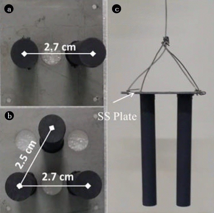
Graphite rods are commercially available, and were used as received. The graphite rods had a length of 10 cm and a diameter of 1 cm (HABO, China). SSP were used as current collectors [19]. Holes with 1 cm diameter were drilled on the SSP to hold the graphite rods. Before application, the SSP were soaked in acetone solution overnight to remove impurities. Graphite rods were inserted into the holes and fixed with conductive epoxy comprised of active carbon powders and modified acrylate adhesive. The top surface of the SSP was covered with modified acrylate adhesive to further fix the graphite rods. In the present research, array anodes with two (A2) and three (A3) graphite rods were fabricated (Fig. 1(a) and (b)). Diametral distance between the graphite rods was determined as 2.7 cm for A2, and 2.7 cm and 2.5 cm for A3, respectively. The fabricated anodes were led out with titanium wire to connect the external resistance (Fig. 1(c)).
2.2. Setup of the SMFC
Sediment inoculum used to form anodic biofilm was collected from the coast of Qingdao city, China. The sediment was filled into a PVC box, achieving a depth of about 15 cm. Overlaying water with a depth of about 10 cm was collected from the same location as the sediment. As prepared array anodes were hand-pressed into the sediment. Cathode was made of three pieces of graphite felt connected together with titanium wire. Each piece of graphite felt had a length of 15 cm and a width of 3 cm. The cathode was soaked in the overlaying water to use dissolved oxygen as electron acceptors. Array anodes shared one cathode, connected through titanium wire with an external resistance of 500 Ω during the startup period.
2.3. Calculation and Analysis
Polarization curves were obtained through changing the external resistance from 20 k to 1 kΩ. Each external resistance was running overnight to achieve steady state and voltage was then recorded with voltmeter. Electric power and current were further calculated according to Ohm’s law. The cathodic potential was simultaneously recorded versus Ag/AgCl (3 M KCl). Anodic potential was calculated as Ecell = Pc-Pa, where Ecell is voltage of the SMFCs, Pc is the cathodic potential, and Pa is the anodic potential.
Cyclic voltammetry (CV) measurement of the biofilm anode was conducted with three-electrode system with anode as working electrode, cathode as counter electrode, and Ag/AgCl (3M KCl) as reference electrode. The CVs were scanned from 0.3 to −0.7 V at a scan rate of 5 mV/s, and five cycles were performed to get repeatable curves, carried out with an 8-channel potentiostate (CHI, the USA).
Electrochemical impedance spectroscopy (EIS) of the biofilm anode was carried out with the same three-electrode configuration as CV measurement. The frequency of EIS analysis was ranged from 105 to 10−1 Hz with amplitude of 5 mV, controlled by a potentiostate (Zahner-Zennium, German). During EIS analysis, the anodic potential was biased at −0.1 V. The EIS data was further processed using equivalent circuit with ZView software.
3. Results and Discussion
3.1. Performance of SMFCs
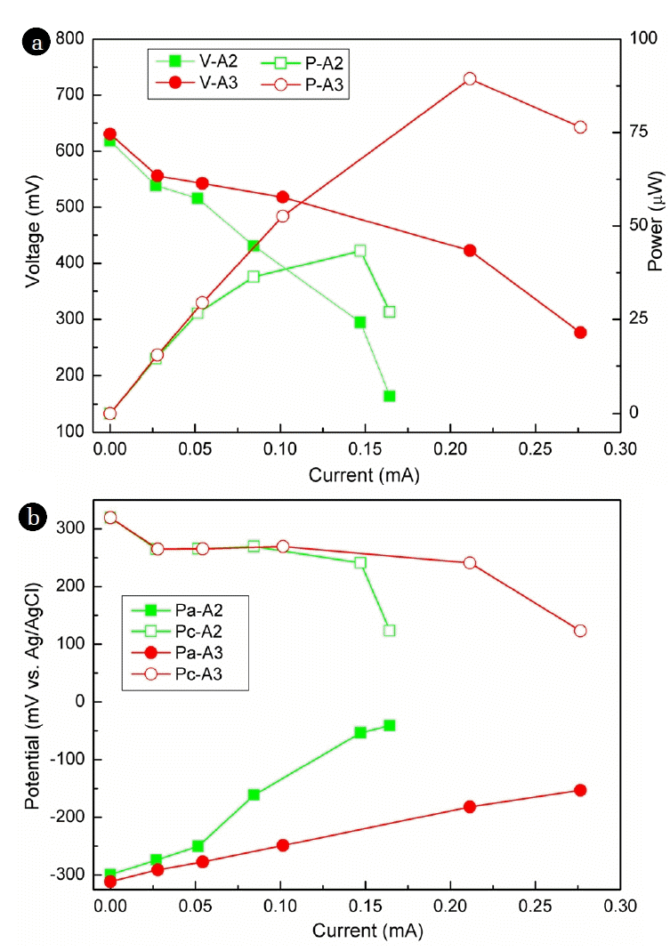
In order to evaluate the performance of the as-prepared array anode, the array anodes were connected to the floating cathode through an external resistance. External resistance was exchanged from 20 kΩ to 1 kΩ to obtain the polarization curve of the whole cells. Meanwhile, electrode potentials were as well recorded. The open circuit voltage was determined with no difference between MFC-A2 and MFC-A3, as around 620 mV (Fig. 2(a)). With decreased external resistance, voltage between SMFC-A2 and SMFC-A3 differentiated, and consequently the current and electric power made a difference. Maximum power (MP) determined from the polarization curves for MFC-A2 was 43.3 μW, at a current of 0.15 mA. With increased number of graphite rods, the MP was promoted to 89.4 μW for MFC-A3, twice that of MFC-A2.
Because the SMFCs shared one cathode, their difference in electric power generation was caused by the difference in anodic performance. Anodic potential was usually recorded to evaluate the electroactivity of the anodic biofilm [20]. In the present research, anodic open circuit potential of MFC-A2 was recorded as −299.3 mV; while it was increased to −41.1 mV at 1 kΩ (Fig. 2(b)). For A3, the open circuit potential was logged as −311.4 mV, determining as −153.2 mV at 1 kΩ. The results implied that more electrons were generated by anode A3 relative to A2 to poise the anodic potential more negative, due to more electrode surface was provided for exoelectrogens to attach on.
Normalized to the anodic surface area, the MP density was determined as 4.4 mW/m2, and 6.0 mW/m2 for MFC-A2, MFC-A3, respectively. The MP density of MFC-A3 was comparable to 8.72 mW/m2 from graphite disk anode [21], 4.5 mW/m2 from carbon fiber anode [22], and 5 mW/m2 from graphite plate anode [12]. MP density generated from MFCs depends on several factors such as the characters of the anode and cathode, and the sediment, reactor configuration, and operation parameters [3, 23–25]. Among the affecting factors, electrode surface area is the key parameter to enhance the power density. It has been revealed that enlarged anodic surface area would result in lower MP density [26]. In the present research, however, the MP density was not reduced as the anodic surface area was increased. The reason for that might be due to the parallel connection of graphite rods reduced the internal resistance. The results demonstrated that the array configuration would benefit for the scale-up of anode and further promoting the practical application of SMFCs.
3.2. Internal Resistance
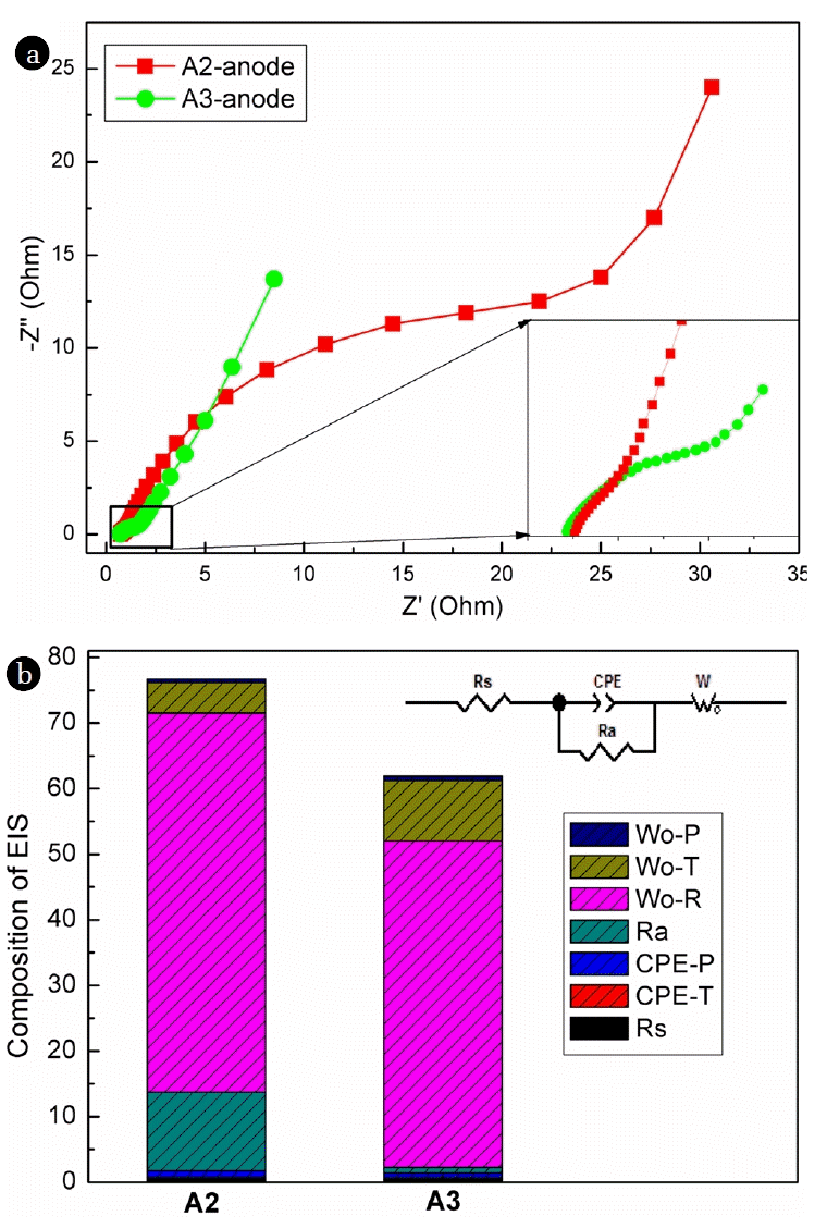
EIS analysis could provide detailed information on composition of electrode internal resistance of MFCs [27, 28]. To confirm that parallel connection of graphite rods benefited to reduce the anodic resistance, EIS analysis was further carried out. The EIS results demonstrated that A2 and A3 had similar resistance composition (Fig. 3(a)). The total internal resistance of A2 was determined as 76.0 Ω, while it decreased to 61.2 Ω when the number of graphite rods increased to 3. More detailed information was revealed through equivalent circuit analysis of EIS (Fig. 3(b)). Solution resistance (Rs) was determined similarly as low as about 0.75 Ω for A2 and A3 because the solution and cathode were shared by all the anodes. The low Rs might be caused by the high conductivity of the seawater as electrolyte, decreasing ion and electron transfer resistance within the bulk solution [29]. Ohmic resistance of the anodes (Ra) decreased with increased number of graphite rod, determined as 11.95, and 0.84 Ω for A2 and A3, respectively. Ohmic resistance relies on the characteristics of the electrode material. Since the same anode material, the decreased Ra of array anode with increased number of graphite rods confirmed once more that the parallel connection benefited the reduction of anodic resistance. Constant phase element (CPE) was caused by the double-layer capacitance resulted from the formation of anodic biofilm. It was revealed that the CPE (CPE-P + CPE-T) of A3 was slightly lower than that of A2, which was calculated as 0.68 F/cm2, and 0.99 F/cm2, respectively. Warburg element occurs because that charge carrier diffuses through the biofilm. In the present study, the Warburg element was determined as 63.0 Ω, and 59.7 Ω for A2 and A3, respectively. Prior research revealed that the formation of electrode biofilm in MFCs would decrease the charge transfer resistance of the biofilm electrode [30]. The results revealed that parallel connection of graphite rods decreased the ohmic resistance of the anode, and promoted the performance of biofilm anode.
3.3. Anodic Polarization
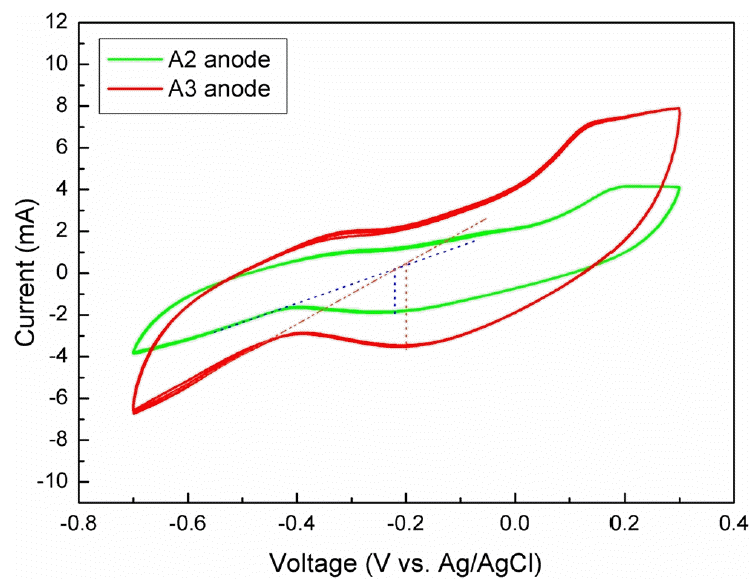
Polarization analysis of single electrode could obtain information on electrochemical reaction on the electrode surface. In the present research CV, a widely accepted electrochemical technique to analyze electrode’s polarization behavior, was adopted to reveal the electroactivity of the biofilm anodes. After 5 cycles’ scanning, the CV curves were well repeated, demonstrating that the polarization behavior of the biofilm anodes achieved steady state (Fig. 4). The peak voltage of A2 was determined as −0.22 V; however, the peak voltage of A3 was located at −0.20 V. The peak voltage was close to the redox potential of exoelectrogens, which was generally determined at 0.0 V to −0.45 V (vs SHE) [31, 32], depending on the species of exoelectrogens and substrate. It was implied that exoelectrogens were successfully accumulated in the biofilm, and generated electrons through decomposing organic matters in the sediment matrix to generate electric current. Peak current could indicate the ability of biofilm electrode to generate electric power. In this research, the peak current was determined as 3.9 mA for A3, about twice 2.1 mA of A2. The larger electric current generated from A3 was due to the more number of graphite rods, generating more background current. Moreover, increased number in graphite rods provided more surface area for exoelectrogens to colonize and generated more electrons to generate electric current.
4. Conclusions
The present research fabricated array anodes with graphite rod as electrode material and SSP as current collector to set up SMFCs. The parallel connection of graphite rods resulted to decreased internal resistance with increased number of graphite rods. Increasing anodic surface area did not decrease, but increased the MP density. It was promoted from 4.4 mW/m2 for two graphite rods to 6.0 mW/m2 for three graphite rods. The advantage of array anode makes it feasible to enlarge the anode, and further set up large-scale SMFCs. Moreover, large-scale array anode would insert into soft sediment via gravity, making it convenient to plant in situ SMFCs, particularly in deep water area. And thus, the presently array design provided an efficient method to prepare large-scale SMFCs with great potential for in situ application.